
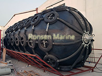
 Floating Pneumatic rubber fenders is type of floating yokohama type pneumatic rubber fenders working as shock absorbers for ship to ship and ship to quay transfers when they come alongside each other on the water. It is made of synthetic-cord-reinforced rubber sheet and compressed air inside to enable it float on the water. Our company, Qingdao Ronsen Marine Supplies Co.,Ltd, are the professional manufacturer of marine airbags, pneumatic rubber fenders, foam filled fenders and offshore buoys in China. Our floating pneumatic rubber fenders are divided into sling tpe, net type, hydro and ribbed types. We manufactured and tested the pneumatic fenders strictly according to International standard ISO 17357-1:2014.
The design and selection of floating fenders can be confirmed as per the maximum energy absorption of specific conditions. We should calculate and compare the requirements for the energy of the following condition. The kinetic energy when the ship berthing or after berthing, the energy of relative motion of ship to ship and ship to wharf.
Ship to ship operation of floating pneumatic fenders
Following the follow chart which simply demonstrate the procedure of floating fenders selection.
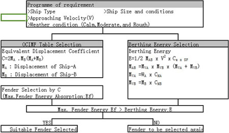
There is a quick reference to do the floating pneumatic rubber fender selection tentatively as per the listed OCIMF table. If the energy absorption of the tentative selected yokohama fender(Ef) is larger than the calculatedd berthing energy (E). It means that a suitable floating fender selection has been made. If the Yokohama fenders energy absorption capacity is less than the calculated berthing energy. The selected yokohama fenders should be upgrated and selected again.
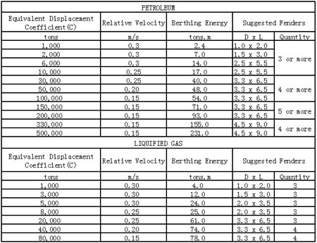
OCIMF Table Selection of Floating Pneumatic Rubber Fenders
It is a quick reference selection based on 50 kPa (Pneumatic 50) and calm condition, Equivalent Displacement coefficient (C) should be calculated firstly, then make the tentatively selection as per OCIMF ship to ship transfer guide.
C= 2 x Displacement ShipA x Displacement ShipB/( Displacement ShipA + Displacement ShipB)
Berthing Energy Calculation of Yokohama Fenders
The berthing energy can be calculated by the following formula:
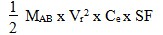
Where:
E =Berthing Energy (in KNm or ton/m)
 = Equivalent Displacement Coefficient
 = Relative Approaching Velocity
 = Eccentricty Factor
SF = Safety Factor
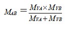
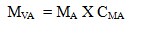
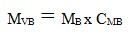
Where:
 = Water displacement of the berthing Ship A ( tons )
 = Water displacement of the berthing Ship B ( tons )
 = Added mass coefficient of Ship A
 = Added mass coefficient of Ship B
Added Mass Coefficient
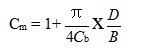 or
or
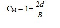
Where:
d = Full load draft (m, ft)
B = Molded Breadth (m, ft)
 = Block coefficient
Safety Factor
A safety factor (SF) value from 1.0 to 2.0 for the berthing energy shall be considered for abnormal berthing conditions.
Eccentricity Factor
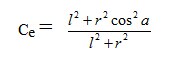
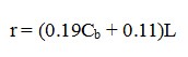
Where:
I = Radius of rotation of the vessel (usually 1/4 of the vessel’s length )
r = Distance of the line paralleled to wharf measured from the vessel’s center of gravity to the point of contact
a = the angle degree
= Block coefficient
L = Length of ship
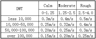
Relative Approaching
The berthing energy needs to be calculated considering weather conditions, categorized by the three conditions calm, moderate and rough, and the approaching velocity to calculate the berthing energy are assumed to be as the follow table. These information are obtained from various industry references and standards.
Ship to Quay Operation of Pneumatic Rubber Fenders
The selection and installation of floating pneumatic rubber fenders (marine fendering) system for a quay is determined based on several design parameters for each ship berthing and mooring condition
The energy can be calculated by the following formula:

Where:
E = Berthing Energy ( in KNm or ton/m)
M = Displacement (ton)
V = Berthing Velocity (m/s)
 = Eccentricity Factor
 = Vitural mas factor
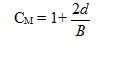
d = Full load draft (m, ft)
B = Molded Breadth (m. ft)
SF = Safety Factor
= Berthing configuration factor
This is the portion of berthing energy which is absorbed by the cushion effect of water between the approaching vessel and the quay wall. The smaller the draft of the vessel is, or the larger the under keel clearance, the mor trapped water can escape under the vessel, and would give a higher value. Also, if the berthing angle of the vessel is greater than 5 degree, we can consider = 1
 = Softness coefficient
This is the portion of berthing energy which is absorbed by the demonstration of the vessel’s hull and fender. When a soft fender is issued = 0.9
We have 3 units floating pneumatic rubber fenders 3.3m x 6.5m ready which is for our client. These fenders are equipped with truck chains tire nets and intial pressure is 50kPa, we take 20 days around to prepare the 3 units peumatic fenders. They are to be shipped to Spain which would be used for the berthing of ships. As the specialized china supplier of marine fenders, we not only supply floating pneumatic rubber fenders but also foam filled fenders, foam filled buoys and marine airbags which are widely used in the oil&gas field.