
FENDER SYSTEMS DESCRIPTION
Marine fenders provide the necessary interface between berthing ships and berth structures. Therefore the principal function of fenders is to transform ships’ berthing energies into reactions which both the ships and berth structures can safely sustain. A properly designed fender system must therefore be able to gently stop a moving or berthing ships without damaging the ship, the berth structure or the fender. Once ships are safely moored, the fenders should be able to protect the ships and the berth structures from the motions caused by wind, waves, current, tidal changes and loading or unloading of cargo. The design of fenders shall also take into account the importance of the consequences, suffered by the ship and the berthing structure in case of excessive ship berthing energy.
Fender systems can be categorised according to the mode by which they absorb or dissipate the kinetic energy of the berthing ship. Below table shows the various major categories of fender systems in common use. As can be seen from the table, most fender systems are based primarily on the principle of the conversion of kinetic energy of the ship into potential energy of the fender. Only a collapsible unit which dissipates the kinetic energy through the plastic deformation of steel or concrete between the fender unit and berth structure, do not utilise this principle. Steel corrugated units are always used in conjunction with another type of fender unit for which it serves as the energy absorbing equivalent of an electric fusc.
Other systems may exist which have either very limited application or have not been widely accepted. Also many existing fender systems are variations or combinations of several of the systems listed. A single or easy solution to all fender problems does not exist. Each combination of vessel, type of berth structure and berthing conditions has different requirements. Factors having impact on the choice of fender are: size of ships, navigation methods, location, tidal differences, water depths, etc. A ship berthing along an exposed berth structure will obviously have other demands on the fender system than if it was to berth along a sheltered berth structure.
Table 3.1 lists the range of standard sizes, energy absorption capacities, reaction forces, rated maximum deflections etc. for the various types of ordinary fender systems in use. All are of the category that converts energy by elastic deformation. Fender factories are constantly carrying out research and developing variations and improvements to these systems, so the fender system designer is advised to consult manufacturers regarding the availability of new fender units. Also, the various fender manufacturers may have different names for fender units of similar appearance and performance characteristics and Table 3.2 does not necessarily include all names for each basic type of fender unit.
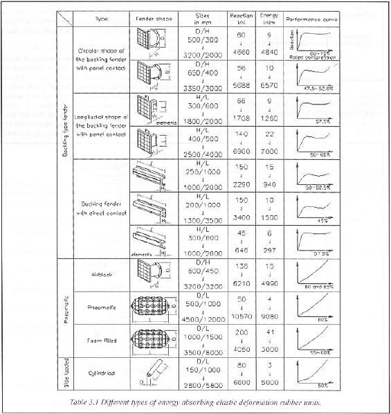
Most of the characteristics listed in Table 3.1 are based on data published by fender unit manufacturers and actual fender performance may vary by as much as ten percent. Also, the characteristics are based on perpendicular impacts, and fender performance may vary considerably when subjected to angular impacts, which is the most common case.
FENDER DESIGN BASIS
Design of a fender system deserves as much attention as the design of any other element of the structure of which it is a part. The selection of fender system and type and the selection of the system of structure should be interactive.
The fender should be designed in such way that:
- Berthing of the vessel to the berth facility takes place without damage;
- The vessel and the berth (including the fenders) do not get damaged when the vessel is moored;
- The periods of operation and safety are extended as much as possible.
The design of a fender system could follow these steps:
- determination of the functional programme of requirements;
- determination of operational aspects;
- assessment of the site conditions;
- assessment of the design criteria;
- calculation of the energy to be absorbed by fender (during berthing or when moored);
- select a suitable fender system and type based on the energy and above criteria;
- determine the reaction force and related friction force;
- check impact of the forces on the structure and on the vessel and the implications of the selected fender for the face of the structure; aspects to be considered are e.g.: The berthing model, geometry for bulbous how and fender spacing are shown on the Vessel Approach Figure 2.3.1, and Island Berths Figures 2.3.2 & 2.3.3.
The above process may have to be repeated several times to select the most optional fender for the specific situation.